Tips on preparing for support
Preparing for support - Help us assist you more quickly
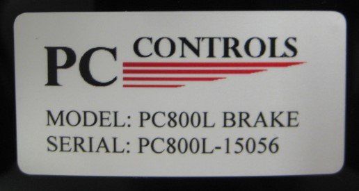
Have the serial number of your control ready for the support team
The serial number is visible either inside the control cabinet or behind the control back cover.
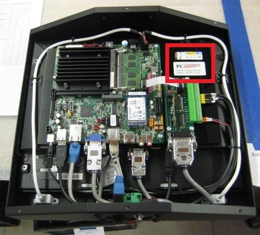
This allows us to quickly reference photos and documentation of your retrofit.
Or you can access your PCC machine serial number by clicking on the Bendwiz tab Parameters/Options/Information
Please review the following list & fill out in detail the questions to prepare for your support call:
PREPARING FOR TROUBLE-SHOOTING BEFORE CONTACTING PC CONTROLS:
1) Have a copy of your PC Control’s electrical drawings available to you prior to calling PCC technical support. Review the drawings to familiarize yourself with your control system. If you don’t have a copy of your electrical drawings, email us at support@pccontrols.net and we will send them to you.
2) Be prepared to replicate the problem during your on-line session with PC Controls. IF you cannot replicate the problem you are experiencing, it makes it very difficult for our technical support team to determine a resolution to your problem.
3) If you are having issues with your safety guarding systems, call your technical support person who installed the safety system and ask them for assistance. If they need PCC assistance, they can call us direct from your machine.
4) Have your PC Controls serial number ready for your support team. This is generally found on control or in the parameters tab in the control software.
QUESTIONS TO ANSWER BEFORE CALLING PC CONTROLS FOR TECHNICAL SUPPORT:
1) Do you have a copy of your PC800 electrical drawings at the machine?
2) When did the issue start occurring?
3) Write down a timeline of events that occurred with the machine problem.
4) Write down any alarms or error messages you are receiving and what is happening on the machine when you receive these error messages.
5) Is the problem consistent from move to move, bend to bend, part to part or is the problem intermittent?
6) Will the back gauge calibrate successfully?
7) Is the hydraulic pump running?
8) Have you done any work on the machine recently, electrically, hydraulically, or mechanically? Have you installed any new parts in the machine?
9) What have you done thus far to address the problem your machine is experiencing?
10) Are you able to calibrate the Ram successfully?
11) Are you able to calibrate each axis of the back gauge successfully?
12) You will need to have someone available who can use a digital multi-meter during the troubleshooting session.
General Trouble-Shooting TIPS:
GENERAL PREPARATION:
• Have a copy of your PC Control’s electrical drawings available to you prior to calling PCC technical support. Review the drawings to familiarize yourself with your control system. If you don’t have a copy of your electrical drawings, email us at support@pccontrols.net and we will send them to you.
• Document and be able to replicate your problem prior to calling PCC technical support.
GENERAL ALARMS & TROUBLE SHOOTING:
• Estop Alarms - Check the estop circuit as defined in your PCC electrical drawings and troubleshoot so as to determine which component in the E-Stop circuit is causing the E-Stop Alarm. Repair/Replace any bad components and retest the circuit.
• Following Errors - A following error indicates that there is an out of tolerance deviation between the targeted position and the actual position determined from encoder feedback. The alarm may be caused by the axis not moving at all when commanded to move or during the move the targeted axis position and actual position deviate.
• Servo Faults - The servo amplifier or motor has encountered a problem with the function of these components. Check motor/servo amp/cable to isolate which one of these is causing the servo fault. Check for power problems, cut or damaged cables, loose connections.
• Overtravel Alarm - One of the machine axis has passed the normal limits of machine axis travel. Check if this condition has occurred and determine why.
PART ACCURACY PROBLEMS:
• Make sure all punches, dies, punch holders, die holders are suited to the type of bending you are doing on the machine.
• Check all your tooling dimensions are entered correctly. Check tooling with a precision measuring instrument.
• If your machine is not building adequate tonnage, check your hydraulic system thoroughly to make sure it is capable of producing the tonnage you are trying to achieve.
• With each tool set you are using, program a test part with a 180-degree bend. Run this part and you will see the punch just kiss the metal. If this is not the result, something in your tooling stack up is incorrect (Top tool holder, Bottom tool holder, Punch, Die). Re-measure each item with a precision measuring instrument and then re-run the 180-degree test part again.
RAM MOVEMENT PROBLEMS:
• Check that proper voltages is being applied to the linear scales (Reference your PCC electrical drawings)
• Check that nothing is mechanically inhibiting the Ram from normal movement.
• Make sure all the mechanical linkages on the machine are in good working and properly lubricated.
BACK GAUGE MOVEMENT/ACCURACY PROBLEMS:
• Check that proper voltages is being applied to the amplifiers (Reference your PCC electrical drawings)
• Check that nothing is mechanically inhibiting each of the back gauge axes from normal movement. Check for proper lubrication of all mechanical components.
• Check for mechanical bind on each back gauge axes.
• If the amount on a part is off consistently, try adjusting the axis calibration/origin position in the parameters tab by the amount that is consistently off.
• Make sure all the mechanical linkages on the machine are in good working order.
MOTOR & DRIVE PROBLEMS:
Servo faults: Check wiring and connections to and from the servo drive & the motor
Check for cuts or kinks in the cables in the motor/drive circuit.
Check that proper voltages are present at each component per your PCC electrical drawings
POWER DISTRIBUTION PROBLEMS:
Check all fuses and circuit breakers in the power distribution circuit outlined in your PCC electrical drawings. Determine the cause of any blow fuses, defective relays or tripped circuit breakers. Replace any faulty wires or components.
PC & CONTROL NOT STARTING UP:
• “No video output” Press the reset button located on the PC motherboard
• Check that you have correct power going to the Video monitor (Reference your PCC electrical drawings)
• Check if the motherboard CMOS battery needs to be replaced
MOTOR & DRIVE PROBLEMS:
• Servo faults: Check wiring and connections to and from the servo drive & the motor
• Check for cuts or kinks in the cables in the motor/drive circuit.
• Check that proper voltages are present at each component per your PCC electrical drawings
Consider preparing for remote support before you call or email
Remote support is often the best way to quickly troubleshoot complex challenges and provide instruction.